|
|
- I'm Online Chat Now
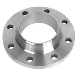
CE Stainless Steel Flange Valves CNC Machining , Stainless Steel Neck Flanges For Pipe
Product Details:
Payment & Shipping Terms:
|
| Body Material: | CF8M / CF8 | Size: | 1/4"- 4” |
|---|---|---|---|
| Connection: | Female Thread | Certificate: | CE And ISO |
| Working Temperature: | —20℃ ~ 200℃ | Sealing: | PTFE |
| Connection Type: | Flange | ||
| Highlight: | ss flange,socket weld flanges |
||
Stainless Steel Flange Valves CNC Machining Stainless Steel Neck Flanges For Pipe
1. DESCRIPTION
Weld Neck Flanges have a long tapered hub and are often used for high pressure applications. When ordering a weld neck flange,
it is important to specify the schedule pipe is being used for. This is because the inside diameter of the flange will match the inside diameter of your pipe.
The buttweld joint this flange has with the pipe along with the tapered hub, makes this flange very resistant to dishing and a very sturdy connection.
These flanges are ideal for extreme fluctuations of temperature and in environments where there may be a lot of bending and handling of the flanges.
2. SPECIFICATION
![]()
Weld Neck Flanges have a long tapered hub and are often used for high pressure applications. The three most common types of facings
that Specialty Flange and Fitting, Inc. carries for weld neck flanges are raised face (most common), flat face, and ring type joint (RTJ).
When ordering a weld neck flange, it is important to specify the schedule pipe is being used for. This is because the inside diameter of the flange
will match the inside diameter of your pipe. The buttweld joint this flange has with the pipe along with the tapered hub, makes this flange very
resistant to dishing and a very sturdy connection. These flanges are ideal for extreme fluctuations of temperature and in environments where
there may be a lot of bending and handling of the flanges. SFF offers these flanges in stainless and alloy material.
3. Key Features:
1. Most common type of high pressure flange
2.Long tapered buttweld hub and the inside diameter of flange matches the inside diameter of the pipe used
3. Preferred in an environment with extreme temperature conditions.
4. DRAWING AND SIZE
![]()
| CL | 150 | 300 | 600 | 900 | 1500 | 2500 |
| DIA A |
30 | 38 | 38 | 38 | 38 | 43 |
| DIA D |
90 | 95 | 95 | 120 | 120 | 135 |
| THK B |
9.6 | 12.7 | 14.3 | 22.3 | 22.3 | 30.2 |
| 11.2 | 14.3 | 20.7 | 28.7 | 28.7 | 36.6 | |
| DIA G |
35.1 | 35.1 | 35.1 | 35.1 | 35.1 | 35.1 |
| DIA K |
60.3 | 66.7 | 66.7 | 82.6 | 82.6 | 88.9 |
| H | 46 | 51 | 52 | 60 | 60 | 73 |
| 47.6 | 52.6 | 58.4 | 66.4 | 66.4 | 79.4 | |
| NO. L |
4 | 4 | 4 | 4 | 4 | 4 |
| DIA L |
15.9 | 15.9 | 15.9 | 22.2 | 22.2 | 22.2 |
| Stud Bolts Diameter x Length | ||||||
| DIA (in) |
1/2 | 1/2 | 1/2 | 3/4 | 3/4 | 3/4 |
| Len mm |
55 | 65 | 75 | 110 | 110 | 120 |
| Other Diameters | |||||||
| NPS | 1/2 | 3/4 | 1 | 1¼ | 1½ | 2 | 2½ |
| 3 | 3½ | 4 | 5 | 6 | 8 | 10 | |
| 12 | 14 | 16 | 18 | 20 | 24 | ||
5. PICTURES
![]()
![]()
ss flange,
socket weld flanges
Contact Person: Monica Ma
Tel: +8613932126769


